Borehole & Well Drilling Services in Kenya: Borehole Drilling Services in Kenya | Borehole Drilling Company | Submersible Pumps | Tanks and Water Towers
Every borehole has a finite operational life. Whether it has been replaced by a more productive well, fallen into disrepair beyond economic rehabilitation, been affected by irreversible contamination, or simply reached the end of its useful service, there comes a point when a borehole must be taken out of service permanently. This process — decommissioning and abandonment — is as technically important as drilling the well in the first place, yet it is one of the most neglected aspects of borehole management.
An improperly abandoned borehole is not an inert hole in the ground. It is an open conduit between the surface and the aquifer — a pathway for contamination that may compromise the water quality of neighbouring wells and the broader groundwater system for years or decades.
Why Proper Abandonment is Essential
The primary environmental concern with an improperly abandoned borehole is vertical cross-contamination: the migration of poor-quality water from shallow, unprotected zones downward through the open borehole into deeper, higher-quality aquifers. This pathway bypasses the natural confining layers that protect deep aquifers and can introduce surface-derived contaminants — bacteria, nitrates, pesticides, hydrocarbons — into drinking water sources.
Secondary concerns include:
Physical hazard: An uncapped, open borehole is a serious physical danger — a fall into a deep, narrow borehole can be fatal. Animals and debris can also fall in and contribute to contamination.
Legal liability: Regulatory frameworks in most jurisdictions require proper abandonment of boreholes that are no longer in use. Failure to comply can result in fines and legal liability for any contamination that results.
Aquifer pressure integrity: In artesian systems, an improperly sealed abandoned borehole can allow a continuous uncontrolled discharge that depletes aquifer pressure over time.
When to Decommission a Borehole
Decommissioning is appropriate in the following circumstances:
The borehole has been replaced by a new well and is no longer needed.
Yield has declined below the minimum usable threshold and rehabilitation is not economically viable.
The borehole is irreversibly contaminated.
The casing or screen has structurally failed beyond repair.
The borehole has been unused for an extended period (typically 5 years or more) with no plans for future use.
Geological or land-use changes have made the borehole incompatible with continued safe operation.
Before a decommissioning decision is finalised, consideration should be given to whether the borehole could be repurposed as a monitoring well — a lower-cost alternative that preserves some value while removing the borehole from active supply use.
Pre-Decommissioning Survey
Before sealing work begins, a pre-decommissioning survey documents the condition and geometry of the borehole. This typically includes:
A downhole CCTV survey to determine the condition of the casing, identify any obstructions or collapsed sections, and confirm the borehole geometry for seal design.
Review of the original completion report to confirm casing depth, screen intervals, and grouting details.
Assessment of water quality in the borehole to determine whether any special handling of formation water is required.
Decommissioning Methods
Complete Grouting (Preferred Method)
The gold standard for borehole abandonment is filling the entire borehole with cement grout from the bottom to the surface. This creates a continuous, impermeable seal that permanently eliminates the borehole as a contamination pathway.
The process involves:
Removal of equipment: The pump, rising main, and cables are removed from the borehole.
Casing perforating or removal (where necessary): If the casing is intact, it may need to be perforated at regular intervals to allow grout to flow outward into the formation and seal the annular space. In some jurisdictions, casing must be removed from the upper section before grouting; in others, grouting through or around the casing is acceptable.
Grout injection: Cement grout is tremied (pumped through a pipe to the bottom of the borehole) from the bottom upward. Grouting from the top by gravity pouring is not acceptable — it creates voids and poor seal quality. The grout pipe is progressively withdrawn as the grout level rises, ensuring complete filling.
Surface completion: The top of the grout column is brought to the surface and the wellhead is capped or removed. A marker post or monument may be installed to identify the location of the former borehole for future reference.
Selective Grouting
Where complete grouting is not feasible (obstructions prevent access to the full borehole depth), selective sealing focuses on the most critical zones:
The upper section — from surface to the bottom of the surface casing — is grouted to prevent surface water ingress.
Any section where different aquifer zones are in hydraulic connection is packed and grouted to restore the natural confinement between aquifer horizons.
Conversion to Monitoring Well
Where the borehole is structurally sound and its location has value for monitoring purposes, conversion rather than abandonment should be considered. The pump and associated equipment are removed, the borehole is redeveloped and disinfected, a monitoring tube is installed if necessary, and a secure monitoring cap is fitted. The borehole is then incorporated into the regional groundwater monitoring network.
Regulatory Requirements and Documentation
Abandonment procedures are regulated in most jurisdictions. The applicable water authority must typically be notified before work begins, and a completion certificate or abandonment report submitted after the work is done. This report should include:
Borehole location and identifier.
Date of abandonment.
Method used and materials placed.
Pre-abandonment survey findings.
Confirmation of surface reinstatement.
A copy of the abandonment report should be retained by the landowner and submitted to the regulatory authority for incorporation into the national groundwater records. Proper documentation closes the administrative life of the borehole cleanly and provides the historical record that may be needed if the site is redeveloped in future.
The Cost of Doing Nothing
Decommissioning has a cost — typically a modest fraction of the original drilling cost — and that cost is sometimes used as a justification for simply leaving an unused borehole uncapped and unattended. This is a false economy. The environmental liability of an improperly abandoned borehole, the cost of any contamination remediation it eventually necessitates, and the regulatory fines that may apply all dwarf the cost of proper abandonment. Like all aspects of borehole management, the right time to plan for decommissioning is before it becomes urgent.
Washing Machine Repair Services in Nairobi | 5 Leading Service Providers
A washing machine is an important appliance in many homes, apartments, hotels, laundries, and businesses in Nairobi. When it stops working, even a simple laundry routine can quickly become a major inconvenience.
Common problems include a washing machine that does not start, fails to spin, does not drain water, leaks, makes unusual noises, or stops during a washing cycle. In some cases, the problem may be caused by a small component, while other faults may require professional diagnosis and replacement of damaged parts.
Fortunately, there are several washing machine repair services in Nairobi that can help diagnose and fix these problems. Professional technicians can work on different washing machine brands and models and provide on-site repair services in many parts of Nairobi.
Below are five companies and service providers that customers can consider when looking for washing machine repair in Nairobi.
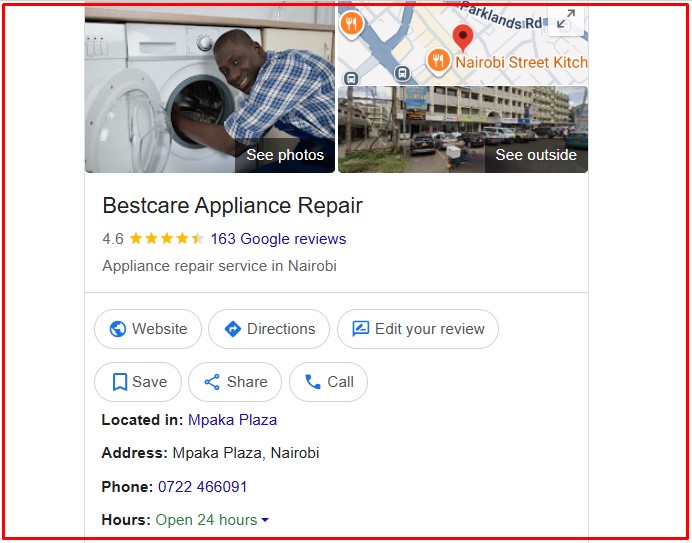
Bestcare Appliance Repair provides home appliance repair services in Nairobi, including washing machine repairs. The company handles both newer and older appliance models.
bestcare appliance repair washing machine repair in nairobi
A technician can inspect the washing machine, identify the cause of the problem, and recommend the appropriate repair.
Services may include mechanical repairs, electrical troubleshooting, replacement of damaged components, installation, relocation, and general maintenance.
Services include:
Washing machine troubleshooting
Washing machine installation
Washing machine relocation
Replacement of faulty parts
Electrical fault diagnosis
General appliance servicing
Preventive maintenance
Service area
Services are available in Nairobi and areas such as Parklands, Ngara, Eastleigh, Embakasi, and surrounding neighborhoods.
For homeowners with several appliances, using an appliance repair company can also be useful when a washing machine needs attention together with other household appliances.
2. Imperial Appliances Kenya
Imperial Appliances Kenya provides washing machine repair services for homes and businesses in Nairobi. The company focuses on diagnosing appliance problems and repairing faulty washing machines.
Its technicians can work on different types and brands of washing machines. Depending on the problem, repairs may involve replacing worn-out parts, repairing electrical components, fixing drainage problems, or servicing the machine.
Imperial Appliances Kenya – Washing Machine Repair Company in Nairobi
Services include:
Washing machine diagnosis and troubleshooting
Washing machine repair
Motor and belt replacement
Drain pump repair and replacement
General maintenance
Faulty component replacement
Emergency repair services
Service area
The company serves Nairobi and surrounding areas, including Westlands, Kilimani, Lavington, Karen, and other neighborhoods.
For customers looking for washing machine technicians in Nairobi, a mobile repair service can be convenient because the technician can inspect the appliance at home.
RepairKE Service Center provides appliance repair services for domestic and commercial customers in Nairobi.
The company offers washing machine diagnosis and repair for both mechanical and electrical problems. Professional diagnosis is important because the same symptom can sometimes be caused by different faults.
For example, a washing machine that does not spin could have a problem with the motor, belt, door lock, control board, or another component.
Services include:
Washing machine diagnosis
Mechanical repairs
Electrical repairs
Parts replacement
Washing machine servicing
Urgent repair services
Domestic and commercial appliance repair
Service area
The company serves Nairobi and nearby areas, including Thika, Ruaka, Kiambu, and other surrounding locations.
MachineRepairNairobi.co.ke provides washing machine repair services in Nairobi for customers experiencing problems with their home appliances.
The service focuses on troubleshooting and repairing common washing machine faults. Technicians can inspect the appliance and determine whether the problem can be repaired or whether a faulty component needs to be replaced.
Services include:
Washing machine repairs
Fault diagnosis
Parts replacement
Washing machine servicing
Drainage repairs
Spin-cycle repairs
Preventive maintenance
Service area
MachineRepairNairobi.co.ke serves customers in Nairobi and surrounding areas.
Customers can use the service when they need a technician to inspect a washing machine that is leaking, making unusual noises, failing to drain, or refusing to start.
5. Nairobi Online
Nairobi Online helps customers find and connect with appliance repair technicians in Nairobi.
The platform can be useful for people who want to arrange washing machine repair without spending a lot of time searching for a technician.
Customers can request repair services and find technicians who serve different parts of Nairobi.
Services include:
Washing machine repair bookings
Appliance repair connections
Access to repair technicians
Home repair services
Appliance troubleshooting
Maintenance services
Service area
Services are available in Nairobi and surrounding suburbs.
When choosing a technician through a repair platform, customers should confirm the technician’s experience with their particular washing machine brand and ask about the expected repair cost before work begins.
A home inspector checking a residential home kitchen.
10 Common Washing Machine Problems That Get Fixed in Nairobi
Washing machines can develop different mechanical, electrical, and water-related problems. Below are some of the most common issues handled by washing machine repair technicians.
1. Washing Machine Not Starting
One of the most common complaints is a washing machine that does not turn on.
The problem may be caused by a faulty power connection, damaged power cable, door lock, control board, fuse, or other electrical component.
A technician can test the appliance and identify the exact cause instead of replacing parts unnecessarily.
2. Washing Machine Not Spinning
A machine may fill with water and wash normally but fail to spin.
Possible causes include a damaged belt, motor problem, blocked system, faulty door lock, unbalanced load, or control-board fault.
A technician can inspect the machine and determine which component is causing the problem.
3. Washing Machine Not Draining
If water remains inside the drum after a washing cycle, the drain system may be blocked or damaged.
Common causes include a blocked drain filter, clogged hose, faulty drain pump, or an object stuck inside the drainage system.
Professional cleaning or pump replacement may solve the problem.
4. Washing Machine Leaking Water
Water leaking from a washing machine should not be ignored. Continued leakage can damage floors, walls, cabinets, and electrical components.
Leaks can come from damaged hoses, door seals, loose connections, detergent drawers, pumps, or other internal components.
A technician can locate the source of the leak and repair or replace the affected part.
5. Washing Machine Making Loud Noises
Unusual banging, grinding, rattling, or humming sounds can indicate a mechanical problem.
Possible causes include worn bearings, loose components, foreign objects, an unbalanced drum, or motor problems.
Early inspection can prevent a small problem from becoming a more expensive repair.
6. Washing Machine Not Filling With Water
A washing machine may fail to fill if there is a water supply problem, blocked inlet filter, faulty inlet valve, damaged hose, or electrical fault.
The technician can check the water supply and test the inlet components.
7. Washing Machine Stops During a Cycle
Sometimes a washing machine starts normally but stops before completing the program.
This can be caused by overheating, drainage problems, water supply issues, door-lock faults, motor problems, or a control-board issue.
Proper diagnosis is important because several different faults can produce the same symptom.
8. Washing Machine Not Heating Water
For washing machines with a heating function, cold water throughout the cycle may indicate a faulty heating element, temperature sensor, wiring, or control component.
A technician can test these components and replace the faulty part where necessary.
9. Washing Machine Shaking or Moving
A washing machine that moves excessively during the spin cycle may be poorly positioned or have an unbalanced load.
However, excessive shaking can also be caused by worn suspension components, damaged shock absorbers, or other mechanical problems.
The machine should be inspected if the shaking continues even after the load is balanced.
10. Washing Machine Showing Error Codes
Modern washing machines often display error codes when they detect a problem.
The code may indicate an issue with the door, water supply, drainage, motor, heating system, or another component.
The correct repair depends on the specific brand and error code. A technician can diagnose the problem and reset or repair the appliance where necessary.
How to Choose a Washing Machine Repair Company in Nairobi
Choosing the right repair technician can save you money and prevent repeated breakdowns.
Before hiring a technician, consider the following:
Check experience
Choose a technician who has experience repairing your washing machine brand and model.
Ask about the problem
A good technician should explain what is wrong with the machine and what needs to be repaired.
Request a quotation
Ask for an estimated repair cost before approving major work. The quotation should indicate whether labor and replacement parts are included.
Check replacement parts
Ask whether replacement parts are genuine, compatible, new, or refurbished.
Consider warranty
If a major part is replaced, ask whether the repair or replacement part comes with a warranty.
Avoid unnecessary repairs
A professional technician should diagnose the problem before recommending expensive replacements.
Washing Machine Maintenance Tips
Regular maintenance can reduce the chances of unexpected breakdowns.
Here are some simple maintenance tips:
Do not overload the washing machine.
Clean the drain filter regularly.
Check water hoses for damage.
Keep the detergent drawer clean.
Use the correct amount of detergent.
Remove coins and other objects from clothes before washing.
Keep the washing machine level.
Leave the door slightly open after use to allow the drum to dry.
Inspect unusual sounds early.
Arrange professional servicing when necessary.
Proper maintenance can improve washing machine performance and may extend the life of the appliance.
Frequently Asked Questions About Washing Machine Repair in Nairobi
1. How much does washing machine repair cost in Nairobi?
The cost depends on the type of fault, washing machine brand, replacement parts required, and technician’s labor charges. Simple repairs may cost less than repairs involving motors, control boards, pumps, or other expensive components.
2. How long does washing machine repair take?
Simple repairs can sometimes be completed during the first visit. More complicated problems may take longer if replacement parts need to be sourced.
3. Can a technician repair my washing machine at home?
Yes. Many washing machine technicians in Nairobi provide mobile or on-site repair services. This is convenient because customers do not have to transport a heavy appliance to a workshop.
4. Which washing machine brands can be repaired?
Professional technicians can often repair many common brands, including Samsung, LG, Bosch, Siemens, Whirlpool, Hisense, Midea, Haier, Electrolux, Beko, Ariston, and other brands. Always confirm that the technician has experience with your specific model.
5. Why is my washing machine not spinning?
A washing machine may fail to spin because of an unbalanced load, damaged belt, motor fault, door-lock problem, drainage issue, or control-board fault. Professional diagnosis can identify the actual cause.
6. Why does my washing machine have water left inside?
Water remaining inside the drum is often caused by a blocked drain filter or hose, a faulty drain pump, or another drainage problem. Cleaning or replacing the affected component may solve the issue.
7. Is it worth repairing an old washing machine?
It depends on the age and condition of the appliance and the cost of the repair. If the repair is relatively inexpensive and the machine is otherwise in good condition, repairing it may be more economical than buying a new one.
8. How often should a washing machine be serviced?
There is no single service schedule for every machine. Regular cleaning and basic maintenance should be done by the owner, while professional servicing can be arranged when the machine develops problems or according to the manufacturer’s recommendations.
9. Should I continue using a leaking washing machine?
It is better to stop using a washing machine that is leaking until the cause is identified. Water can damage floors and electrical components and may create a safety risk.
10. How can I find the best washing machine repair service in Nairobi?
Compare technicians based on experience, reputation, availability, pricing, warranty, and experience with your washing machine brand. Ask for a diagnosis and quotation before approving major repairs.
A faulty washing machine can quickly disrupt your daily routine, but many common problems can be repaired by an experienced technician. From machines that fail to start or spin to drainage problems, leaks, unusual noises, heating faults, and error codes, professional washing machine repair services in Nairobi can help restore your appliance.
Imperial Appliances Kenya, Bestcare Appliance Repair, RepairKE Service Center, MachineRepairNairobi.co.ke, and Nairobi Online are options for customers looking for appliance repair assistance in Nairobi and surrounding areas.
When choosing a repair service, consider the technician’s experience, the quality of replacement parts, repair costs, warranty, and availability of on-site service. Regular maintenance can also help prevent breakdowns and keep your washing machine working efficiently for longer.
For reliable washing machine repair in Nairobi, it is always best to have the appliance properly diagnosed before replacing expensive parts or deciding to purchase a new machine.
Drilling a borehole creates a hole in the ground — but it does not automatically create a functioning well. Before a borehole can be put into productive use, it must be developed. Borehole development is the process of removing fine particles, drilling debris, and damaged formation material from the immediate vicinity of the borehole wall and screen. Done properly, it increases hydraulic conductivity, improves water clarity, and maximises the long-term yield of the well.
Why Development Matters
During drilling, the borehole wall becomes clogged with drill cuttings, mud filtrate, and disturbed formation material. In rotary mud drilling, a filter cake forms against the formation that actively reduces water inflow. Even in air-drilled boreholes, fine particles migrate into the gravel pack and screen slots during construction. If these materials are not removed, the borehole will deliver less water than the aquifer is capable of providing, and it will deteriorate faster over its operational life.
Development works by reversing or alternating the flow of water across the borehole screen, dislodging fine particles and carrying them to the surface for removal.
Surging
Surging is one of the oldest and most effective development methods. It involves rapidly moving a tight-fitting piston or surge block up and down inside the borehole casing. The back-and-forth motion creates alternating pressure surges that push and pull water through the screen and gravel pack, loosening fine material and drawing it into the borehole where it can be bailed or pumped out.
Surge blocks can be solid (closed-face) or valved (open-face). Valved surge blocks allow water to pass through on the downstroke, intensifying the surging action on the upstroke. The process is repeated across different depth intervals, progressively working from the bottom of the screen upward.
Surging is particularly effective in unconsolidated formations such as alluvial sands and gravels. It is low-cost, requires no specialised equipment beyond the surge block and a cable or drill string, and can be highly effective when carried out systematically with regular bailing between surge cycles.
Jetting
Jetting uses high-velocity water directed through a nozzle to break up bridging and compaction around the borehole screen. The jetting tool is lowered into the borehole and rotated while water is pumped at high pressure through nozzles aimed horizontally at the screen perforations and surrounding gravel pack.
The hydraulic force disrupts fine particle bridges that have formed across screen slots and penetrates further into the formation than surging alone. Jetting is often combined with simultaneous pumping from the borehole, so that dislodged material is immediately removed rather than allowed to resettle.
This method is especially useful in boreholes with fine-grained formations where surging may not be aggressive enough, and in rehabilitation of older boreholes where screen blockage is a primary problem. The equipment requirements are more substantial — a high-pressure pump, rotary jetting tool, and swivel assembly — but the results in problem formations are often superior.
Air Lifting
Air lifting introduces compressed air directly into the borehole below the water table. The air mixes with water, creating a buoyant air-water mixture that rises rapidly to the surface, drawing formation water behind it and generating a vigorous flow across the screen and into the borehole.
The surge created by intermittent air injection — pumping air in pulses rather than continuously — is particularly effective at dislodging fine material. Air lifting can be combined with a swabbing tool or with jetting for a more aggressive development programme.
Air lifting has a major practical advantage: it does not require submersible pump equipment in the hole during development, making it simple to observe and control. It is widely used in air-drilled boreholes where a compressor is already on-site from the drilling operation, making it a cost-efficient first development step.
Combining Methods for Best Results
In practice, the most effective borehole development programmes combine two or more of these methods. A typical sequence might begin with air lifting to clear the bulk of drilling debris, progress to surging to break up compacted zones, and finish with jetting to clear stubborn screen blockages. Between each stage, the borehole is pumped to remove mobilised fines, and the turbidity of the discharged water is monitored. Development is considered complete when the water runs clear and the yield stabilises.
The investment in thorough borehole development directly determines the operational performance and lifespan of the well. Skipping or shortcutting this phase is a common and costly mistake.
A borehole that underperforms its potential is a frustrating and costly outcome. Whether caused by poor construction, inadequate development, or suboptimal design, low yield can often be improved — sometimes dramatically — through targeted optimisation techniques. Understanding these methods allows project managers and hydrogeologists to extract maximum performance from an existing asset before resorting to the expense of drilling a new well.
Understanding Yield Limitations
Before applying any optimisation technique, it is essential to diagnose the root cause of poor yield. The two primary categories are:
Aquifer limitations — the formation genuinely cannot supply more water, due to low permeability, poor recharge, or over-abstraction in the area.
Borehole inefficiency — the aquifer has greater capacity than the borehole is accessing, due to screen blockage, poor development, inadequate penetration, or skin damage around the borehole wall.
Distinguishing between these two causes requires careful analysis of pumping test data, step drawdown tests, and specific capacity measurements. Optimisation techniques are effective primarily in the second category.
Enhanced Development
The most straightforward yield optimisation measure is completing or intensifying the borehole development process. Many boreholes are under-developed — either because the initial development programme was too short, or because fine material has continued to migrate into the screen zone after commissioning.
Repeating or extending development using surging, jetting, or air lifting can remove residual formation damage and improve hydraulic connectivity between the aquifer and the borehole. In many cases, a single day of aggressive redevelopment can increase specific capacity by 20–50%.
Acidisation
In limestone, dolomite, and other carbonate formations, weak acid (typically hydrochloric acid at 10–15% concentration) can be injected into the borehole under pressure. The acid dissolves carbonate minerals along fractures and in the pore matrix near the borehole wall, enlarging flow pathways and removing calcite encrustation that may be blocking natural fractures.
Acidisation is a standard technique in oil and gas well stimulation and is increasingly applied in water well engineering where geology permits. It requires careful handling of hazardous chemicals, neutralisation and disposal of spent acid, and thorough post-treatment flushing before the borehole is returned to service.
Hydrofracturing (Hydraulic Fracturing)
Hydrofracturing involves injecting water at high pressure into a sealed section of the borehole to create or extend fractures in hard rock formations. The process uses packer equipment to isolate a target zone, then pressurises that zone beyond the fracture threshold of the rock, propagating new fractures outward into the aquifer.
This technique is most effective in crystalline basement rocks — granites, gneisses, and quartzites — where groundwater is stored in fractures rather than pores. Hydrofracturing does not create water where none exists, but it can dramatically improve connectivity between the borehole and existing water-bearing fractures. Success rates vary, but yield improvements of two to ten times are documented in suitable geological settings.
Screen Replacement or Extension
Where yield limitations are linked to inadequate screen length, blocked screen slots, or a screen positioned in the wrong zone, mechanical intervention may be necessary. In some designs, the screen can be extended downward to penetrate a deeper productive zone, or replaced with a screen of larger open area or more appropriate slot size for the formation.
This is an intrusive and relatively expensive intervention but can be justified where the aquifer potential clearly exceeds what the current construction allows.
Pump Optimisation
Yield is not solely a function of the aquifer and borehole — the pump selection and drawdown management also play a role. Operating a pump at a rate that exceeds the safe yield causes excessive drawdown, air entrainment, and pump damage. Conversely, a correctly sized pump that maintains drawdown within the optimal range maximises sustained yield without stressing the system.
Variable speed drives (VSDs) allow pump output to be matched dynamically to aquifer response, improving overall efficiency and reducing wear. In boreholes with moderate yields, step-pumping regimes — cycling between pumping and rest periods — can deliver more total water over a day than continuous pumping at a rate the aquifer cannot sustain.
Long-Term Perspective
Yield optimisation is most successful when combined with ongoing monitoring. Regular measurement of rest water levels, pumping water levels, and specific capacity provides early warning of declining performance and allows corrective action before problems become severe. The best-performing boreholes are those that are actively managed, not simply installed and forgotten.
Groundwater drawn from a well-constructed borehole is generally of good microbiological quality. However, the process of drilling, development, and installation inevitably introduces bacteria, organic material, and surface contamination into the borehole. Before any water is used for human consumption, the borehole must be thoroughly disinfected. Disinfection is not a substitute for good construction — it is a final safeguard that ensures the borehole is bacteriologically safe at the point of commissioning.
When Disinfection is Required
Disinfection is mandatory in the following circumstances:
After initial construction — before any first use of the borehole.
After any maintenance or repair work — whenever tools, pumps, or materials have been introduced into the borehole.
After rehabilitation — following redevelopment or screen replacement.
After a period of non-use — boreholes left idle for extended periods can develop bacterial populations.
After suspected contamination — if a positive coliform test or other microbiological indicator is detected.
Disinfection Agent: Chlorine
Chlorine is the standard disinfection agent for boreholes, applied either as:
Sodium hypochlorite (liquid bleach) — typically 5–12% available chlorine, widely available and easy to handle.
Calcium hypochlorite (granular or tablet form) — typically 65–70% available chlorine, more concentrated and easier to store and transport.
The target is to achieve a free residual chlorine concentration of at least 50 mg/L (50 ppm) throughout the borehole water column, which is sufficient to kill the vast majority of waterborne pathogens including E. coli, Salmonella, and enteric viruses.
Step-by-Step Disinfection Procedure
Step 1: Calculate the Volume of Water in the Borehole
Determine the volume of standing water in the borehole using the casing diameter and the depth from the water table to the bottom of the casing. The formula is:
Volume (litres) = π × (radius in metres)² × water depth (metres) × 1000
Step 2: Calculate the Required Chlorine Dose
To achieve 50 ppm free chlorine, calculate the mass of active chlorine needed based on the water volume. Account for the concentration of the chlorine product being used.
For example: achieving 50 ppm in 500 litres requires 25 grams of active chlorine. If using 70% calcium hypochlorite, this equates to approximately 36 grams of product.
Step 3: Prepare and Introduce the Chlorine Solution
Dissolve the calculated quantity of chlorine in a bucket of clean water before introducing it into the borehole. Pour or pump the solution down the full depth of the borehole, ensuring distribution throughout the water column. Lower the solution along the borehole walls to treat the casing surfaces.
Step 4: Circulate and Agitate
Surge the borehole using the pump or a bailer to circulate the chlorinated water throughout the water column and into the gravel pack and screen zone. The chlorine solution must make contact with all surfaces.
Step 5: Contact Time
Allow the chlorine solution to remain in contact with the borehole for a minimum of 12 hours, and preferably 24 hours. Do not pump or use the borehole during this period.
Step 6: Flush the Borehole
After the contact period, pump the borehole to waste until the chlorine smell dissipates and a field test confirms residual chlorine has dropped to below 0.5 mg/L. Do not discharge the chlorinated water into watercourses or in quantities that could damage vegetation.
Step 7: Bacteriological Testing
Following flushing, collect a water sample for laboratory bacteriological analysis. The borehole should not be brought into service until test results confirm the absence of total coliforms and E. coli.
Special Considerations
In boreholes with confirmed iron or manganese bacteria (Gallionella or Leptothrix species), standard chlorine disinfection may need to be preceded by a shock treatment with higher concentrations. Biofouling of this type is resistant to normal doses.
Where a pump is installed, the pump and rising main must be removed or treated in situ to ensure all equipment surfaces are disinfected along with the borehole.
Documentation
A disinfection record should be maintained for every borehole, noting the date, chlorine product and dose used, contact time, flushing time, and the results of post-disinfection bacteriological testing. This record forms part of the borehole completion documentation and is essential for ongoing compliance and quality assurance.